Research Division
Reprinted from "INSULATORS - Crown Jewels of the Wire", July 1979, page 30
The following item was sent in by Dick Bales of Aurora, Illinois. It is reproduced
from Telebriefs, September 1977, the little newsletter of Illinois Bell.
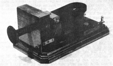
Thumper
phone was "voice powered" (no batteries). People had to shout.
No
cotton tail on this "Thumper"
The first commercial telephones were
installed in the country in May, 1877. They had a very basic flaw. To signal,
the caller had to poke a stick through the mouthpiece and tap a diaphragm
inside. Poke too hard and you broke the phone.
Thomas Watson turned his
attention to the problem and by June, the first telephones with built-in signaling
devices were being installed.
A small hammer was mounted inside the phone.
Pushing a button caused the hammer to hit the edge of the diaphragm. It wasn't a
very good solution. The "thumping" noise it produced wasn't very loud.
Next came buzzers and then bells.
There are very few original Watson
"Thumper" phones still in existence. You can see one at Illinois
Bell's Telephony Museum, 225 W. Randolph St., Chicago. The model on display is
on loan from the Smithsonian Institution.
Dear Mrs. Harried:
I am enclosing
several pages from the book American Telegraphy & Encyclopedia of the
Telegraph., Maver Publishing Company, 1912. In the text of the material are some
additional points relating to the story on insulator bugs by Larry Larned, Crown
Jewels, 12-77, page 13. From this account, it is evident A.T.& T. Co.
engineers may have been wise to research out the success of porcelain insulators
in the telegraph industry, already some 55 years old at the time the
transcontinental telephone line was built.
Michael L. Johnson
- - - - - - - - - -
pg.
538
American Telegraphy.
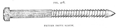
known as
Fetter drive screws. The pins for the support of the Insulators are placed on the
cross-arms in advance. Locust pins are the most durable and most capable of
withstanding heavy strains. The cross-arms and pins should be painted before
their erection on the poles. In some cases they are simply dipped in paint, but
this has not been found a durable method of applying the preservative.
Specifications generally state the exact manner in which these details are to be
executed.
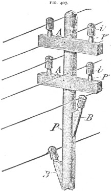
The number of wire to be strung on the poles having been determined in
advance the desired size and the number of cross-arms is arranged for. For
telegraph purposes 2, 4, or 6-pin cross-arms are most frequently used, as arms
of those sizes allow a larger space between the wires. In putting up cross-arms
on lines of all kinds the arms should be reversed on every other pole; that is,
the "gains" should be on one side of one pole, and on the other side
of the next pole, as one looks along the line. This tends to keep a uniform
strain on the poles.
Insulators. -- Some of the essentials of an insulator, for
aerial purposes, are that it shall have high electrical resistance, shall
possess strength, permit a good hold upon the wire, shed rain freely, have no
dark recesses for the accommodation of insects, and be reasonably cheap.
As
these requirements are found but rarely in any one substance it is evident that
the available materials are limited. For instance, iron would possess strength,
but it is not an insulator, and glass possesses non-conducting qualities but is
more or less brittle. A combination of both might possess strength and high
insulation but would be opaque.
In Europe, porcelain and earthenware
insulators are very extensively employed and are highly esteemed. They have also
been used in America, but at the present time and for many years past a glass
insulator is and has been practically the only one employed in the telegraph,
and, it may be added, the telephone service.
It is claimed for porcelain and
earthenware insulators of the higher grades that, besides possessing, normally,
higher electrical resistance than glass insulators, in moist and damp weather,
they do not accumulate, on their surfaces, moisture, to the same extent as glass
and, therefore, that they are a much superior insulator than glass at such
times. On the other hand, it has been observed, in this country, that vermin are
more apt to build in the recesses of the porcelain insulators than in the glass,
(presumably owing to the greater opacity of the former), and, also, that,
apparently, soot adheres more firmly to the former than to the latter, both of
which, it is well known, tend to reduce the insulation, especially in wet
weather. Doubtless, however, the greater cost of porcelain and earthenware,
especially the former, as compared with glass, has been an important factor in
preventing a more general use of those materials as insulators, in this country.
Experience has, however, also shown, in this country, that, given a wire free
from foliage, kite tails, etc., the occasions are rare when a line well
insulated with glass will not work fairly successfully in ordinary wet weather.
On repeated occasions the writer has found that certain long overhead circuits
which, within city limits, were practically useless, owing to low insulation,
when tested outside of those limits were found to be in good working order.
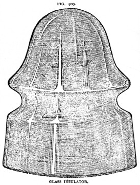
The
styles of the "American" glass insulator vary in numerous ways,
namely: as to its shape, the location and depth of the groove for the wire, the
depth of the hole for the pin, the number and depth of the screw-threads within
the insulator for the pin, etc., but its general appearance will be seen in
Fig's. 409, 410. The latter is known as the "B and O" insulator; its
weight is about 22 ounces.
A smaller insulator of the same general form, termed
a "pony" insulator, Fig. 411, is much used for No. 12 B.W.G.
hard-drawn copper wire.
The location and depth of the wire groove requires
consideration. If it is too shallow, the "tie" wire slips out easily.
If too deep, the strain of the tie wire is apt to crunch the glass, thereby impairing
the insulation; in fact, introducing a source of defective insulation,
often very difficult to discover. The lower the groove on the insulator the less
is the strain on the supporting pin, but at that point the glass is thinnest.
The bell shaped form gives a good water shed and tends to throw the
"drip" away from the pin.
In order, further to keep the pin dry, some
insulators are made with a double "Petticoat," as seen in Fig. 412, in
which a section of the lower part of the insulator is removed to show the double
petticoat. This insulator is known as the W. U. "double petticoat"
insulator. In Fig. 413 is shown a form of insulator designed to still further
increase the insulation of the insulator by decreasing its surface where it
would come in contact with the line wire and "tie" wire. It also
facilitates the cutting of the tie wire; that is, the piece of wire which ties
the line wire to the insulator. Economy is also aimed at reducing the weight of
the glass without materially decreasing its strength. The manner which both of
these results are designed to be effected will be obvious on examining the
illustration. In Fig. 410 the tie wire is passed around the upper groove. The
bulge above the upper groove is designed to throw off the water from the wire
and pin. The object sought in running the pin so far up in the bell is that, in
case of the breaking of the glass, the tie wire may still be held by the pin
upon the cross arm.
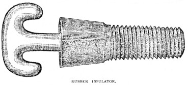
A rubber insulator in which an iron hook is inserted,
as shown in Fig. 414, is used extensively on the underside of cross-arms, in
cities, especially on house-top fixtures.
Tree Insulator. -- When from any cause
whatever it is found impracticable to pass beneath or to surmount a grove of
trees so as to avoid the foliage, it will be necessary to use insulated wire
through that portion of the route.
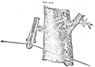
In isolated cases, where the owner will not
permit the placing of insulators on trees to ward off the wires from the trunk
or boughs, a tube of vulcanized rubber placed over the wire has been found of
much utility.
An insulator designed for attachment to trees is shown in Fig.
415. It may be fixed at any desired angle. The manner of its application will be
obvious by a glance at the drawing.
Wire Stringing
Although hard-drawn copper
wire has been found to give very satisfactory service as an aerial telegraph
wire, it is still thought advisable to some telegraph engineer, in the
construction of a line of that wire, to strengthen it by the use of one or more
iron wires.
As to the manner of placing the iron wires to obtain best results,
opinions differ. When but one iron wire is used, however, a No. 6 or 8 B.W.G.
iron wire is generally placed on a pin on the top of the pole. When more iron
wires are used, it is, by some, considered advantageous to erect, first, a 4-pin
cross-arm, and on this to string a No. 6 B.W.G. iron wire, each side of the
pole, stringing the copper wires on the adjacent pins. If the line is a heavy
one
this process may be repeated, say, every third or fourth cross-arm.
Assuming the copper wires to be No. 14 B.W.G., No. 6 iron wire could be used, in wire
"patching," interchangeable with the copper wire, the electrical
resistance of each being nearly alike, namely, about 8.5 ohms.
The poles,
cross-arms, etc., having been placed in position and the poles thoroughly
guyed, the men engaged in stringing the wire follow up, closely. This force con...
|

)
)
)
)
)
)
)
)
)
)